ENGINE
MANAGEMENT SYSTEM DIESEL


Subsections of the diesel injection system


Differences between diesel and gasoline engines
Major
Differences between Diesel and Gasoline Engines Being as
Compression Ignition (CI) engines only draw in air, they are able to compress
this to a level which is considerably higher than that in the spark ignition
engine (SI) using an air fuel mixture.
With its overall efficiency figure, the diesel engine rates as the most
efficient combustion engine. The resulting low fuel consumption, coupled with
the low level of pollutants in the exhaust gas and the considerably reduced
level of noise, all serve to underline the diesel engine's significance.
Development
Steps of Diesel Engine Control Systems
Higher
and higher demands are being made on the diesel engine's injection system as a
result of the increasingly severe regulations governing exhaust and noise
emissions and the need for lower fuel consumption. Looking at the engine
control system in the beginning, the control was made by mechanical means, such
as the distributor pump. With this systems it was very difficult to acquire
optimal engine efficiency with simultaneously satisfying emission control
regulations. The next development stage
was the Electronically Controlled Distributor Pump (COVEC-F) from Zexel. The
latest generation of diesel injection system is the Common Rail Direct
Injection (CRDI) which nowadays consist
of various sensors detecting the
operating conditions of the engine. Actuators
are used to influence the operating conditions accordingly, both processed by an electronic device, the
control unit. The control unit is processing the data acquired by the sensors
in order to determine the best operating conditions and then drives the
actuators accordingly. Lets start with the basic engine operation to understand
the control requirements precisely.
Basics about combustion
Basics about combustion

As mentioned
before, the Diesel Engine is a Compression Ignition (CI) engine. The mixture is
usually formed inside the combustion chamber. The injectors are installed
inside the cylinder head and inject the fuel directly into the combustion
chamber, in which it mixes with air. During the first stroke, the downward
movement of the piston draws in un-throttled air through the open intake valve.
During the second stroke, the so called compression stroke, the air trapped in
the cylinder is compressed by the piston (32-55bar) which now is moving
upwards. The compression ratio is around 25:1.
In this process, the air heats up to temperatures around 800C°. At the
end of the compression stroke the nozzle injects fuel into the heated air. The
injection pressure varies between 250 – 1600 bar, depending on engine load
condition and injection system used. Following the ignition delay, at the
beginning of the third stroke the finally atomized fuel ignites as a result of
auto ignition and burns almost completely. The cylinder charge heats up even
further and the cylinder pressure increases again. The energy released by the
combustion is applied to the piston. The piston is forced downwards and the
combustion energy is transformed into mechanical energy. In the fourth stroke, the
piston moves up again and drives out the burnt gases through the open exhaust
valve. A fresh charge of air is drawn in again and the working cycle is
repeated.

Diesel
Fuel
Diesel or
Diesel fuel is a specific fractional distillate of fuel oil (mostly petroleum)
that is used as fuel in a diesel engine.
As a hydrocarbon mixture, it is obtained in the fractional distillation
of crude oil between 250 °C and 350 °C at atmospheric pressure.
Diesel fuel is considered to be a fuel oil and is about 18% denser than
gasoline. Diesel fuel, however, often contains higher quantities of sulfur. In Europe , emission standards have forced oil refineries to
reduce the level of sulfur in diesel fuels since they are harmful for the
environment. Sulfur prevents the use of catalytic diesel particulate filters to
control diesel particulate emissions. However, lowering sulfur also reduces the
lubricity of the fuel, meaning that additives must be put into the fuel to help
lubricate injection system components. Diesel contains approximately 18% more
energy per unit of volume than gasoline, which, along with the greater
efficiency of diesel engines, contributes to fuel economy.
Bio-Diesel
Bio-Diesel
can be obtained from vegetable oil and animal fats. Bio-Diesel is a non-fossil
fuel and consists of alkyl (usually methyl) esters instead of the alkane and
aromatic hydrocarbons of petroleum derived diesel.
Influence of mixture composition
Influence of mixture composition
A variety
of different combustion deposits are formed when diesel fuel is burnt. These
reaction products are dependent upon engine design, injection system design,
engine power output and working load. In the first place water (H2O) and harmless carbon dioxide (CO2) are generated. In relatively low concentrations, the following
substances are also produced:
- Carbon monoxide (CO)
- Unburned hydrocarbons (HC)
- Nitrogen oxides (NOx)
- Sulfur dioxide (SO2) and sulfuric acid (H2SO4)
- Soot particles
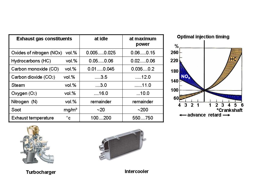
When the
engine is cold, the exhaust gas constituents which are immediately noticeable
are the non oxidized or only partly oxidized hydrocarbons which are visible in
the form of white or blue smoke, and the strongly smelling aldehydes.

Influence
of mixture composition
The
following contribute to the reduction of fuel consumption and exhaust gas
emissions:
- Fuel atomization (high injection
pressures)
- Injection sequence characteristics
- Precision manufactured injection nozzles
- Fuel injection pumps with precise fuel
metering
- Modified combustion chambers
- Precisely defined fuel spray geometry
Apart
from the above mentioned points, optimal injection timing is decisive for
reducing exhaust emissions in a diesel engine. The start of combustion is
primarily determined by the start of injection. Retarded injections reduces
emissions of oxygen and nitrogen. Over retarded injections increases the
emission of hydrocarbons. Deviations of the start of injection from the
nominal value by 1° of crankshaft angle
can increase the emission of NOx or HC by approximately 15%.
This high
sensitivity requires that the start of
injection is precisely set. The most favorable setting for the start of
injection can be precisely maintained by an electronic controlled system.
Turbocharger/Intercooler
As the
temperature of the intake air increases on engines with turbochargers, there is
a rise in the combustion temperature and thus in the emission of oxides of
nitrogen. In engines fitted with turbochargers, the cooling of the compressed
air is an effective way of reducing the formation of oxides of nitrogen.
Another way for reducing NOx is to use Exhaust Gas Recirculation (EGR).

Subsections of the diesel injection system
- Fuel Delivery System,
including fuel tank, supply lines, fuel filter, pre-supply pump (either
electrical type or mechanical type), high pressure pump and high pressure
pipe.
- Start Assist System,
including glow plugs and glow plug control unit (either separate or
located inside the Engine Control Module)
- Air Induction System,
including Air Filter and Exhaust Gas Recirculation
- Exhaust System, including
Oxidation Catalyst and Particulate Filter (only CRDI)
- Electronic Control System,
including Sensors and Actuators (only Electronically Controlled
Distributor pump and CRDI)
- Vacuum System
Fuel filter and water separator
Water Separator Warning LampThe increasing number of diesel engines used in passenger cars has led to the demand for an automatic warning device which indicates to the driver when water must be drained out of the fuel filter.Water Drain ProcedureThe Diesel Injection System needs a fuel filter with water reservoir, from which water must be drained at regular intervals or when the water separator warning lamp is illuminated. Open the drain plug to drain the water from the water reservoir. If no water comes out, open the air bleeding plug on top of the filter element. Please refer to the Shop Manual for more detailed information.

Fuel
Filter replacement
- Clean the Filter housing
- Remove the filter element by
turning it counter clockwise
- Clean the filter contact
surface
- Install the new filter
element, tighten it by turning it clockwise, refer to the shop manual for
detailed information about the tightening torque
Air
Bleeding
It is
required to bleed the system if any component within the diesel system was
replaced. If there is air present within the system, the engine is hard to
start or will run roughly. The air
bleeding procedure differs from model to model. Therefore refer to the Shop or
Owners Manual for more detailed information.
Pressure
Relief Valve
Certain
filters (for example Bosch CRDI) incorporate a Pressure Relief valve located on
top of the fuel filter assembly. In case of a restriction inside the filter or
at the filter outlet side, the pressure relief valve opens, thus allowing the
fuel to flow back into the fuel tank.


 ‘V’ type design, angle 60-90º
 • Engine Design like In line
 • Used Two Cylinder Head
 •Energy is define as the ability to do work


